Map Content
This section describes the components of the contents of the map.
Map content consists of the following tabs:
Layers
The Layers tab shows the layers that are currently available in the map window. In other words, the Layers tab acts as the map's legend.
The order of items in the Layers tab reflects the sequence of layers corresponding to the items on the map. The first element (top) in the list corresponds to the layer on the map located on the top.
To change the order of the layers on the map, use drag and drop to change the order of the corresponding elements in the Layers tab.
You control the display of a layer with a check box next to the item name in the layers. Check the box to display the layer, and clear the box to turn off the corresponding layer on the map.
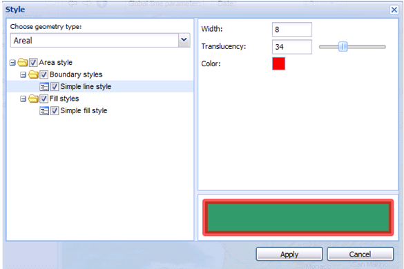
To change the style display for a layer on the map, click the pictogram for the selected layer. In the Style dialog box, check a geometry type (for example a boundary style) appropriate for a given layer; then define the style using the available controls.
To restore the default style for the selected layer, right click and select Restore default style.
![]() Functionality for changing the style for displayed layers is accessible only for layers that come from services which support style changing.
Functionality for changing the style for displayed layers is accessible only for layers that come from services which support style changing.
Defining a pattern fill:
For geometries of area type, you can define a pattern fill apart from the simple fill style. To define a pattern, fill in the Style dialog box, select the Simple fill style, and then type the path to the images library in the Library address field. (The library address should contain the URL path to the virtual directory containing the images or the folder name with images in the application folder that has been defined by the administrator.) In the Picture field, all pictures for the provided libraries are visible. Select a picture that should be used as a pattern fill, and then click Apply to set the pattern fill for all objects of the selected feature class. Translucency for the pattern fill can be defined as well as for the simple fill style.
When the pattern fill is defined, the color attribute is not applied.
Setting image as a point style:
For features with the point geometry type, you can also define a simple point style and graphic style. To define the graphic style in the Style dialog box, select Graphic style from the Type drop-down list, and then type the path to the images library in the Library address field. (As The library address should contain the URL path to the virtual directory containing the images or the folder name with images in the application folder that has been defined by the administrator.) In the Picture field, all images for the provided libraries are visible. Select an image that should be used as a point style.
Use the Size field to adjust the size of the image. Use the Rotation field to define the value in degrees for the image (symbol) rotation. The image is rotated in a counter clockwise direction. To rotate the symbol in a clockwise direction, use negative values.
The symbol preview is visible in the Style dialog box. Click Apply to use a defined graphic style for all objects of a selected feature class. Translucency and color attributes for the graphic style are not applied.

You can define layer properties such as display mode, locatability, translucency, format, and so forth. The properties you can set depend on the service (data source). Settings for layers are available in the context menu for the selected item.
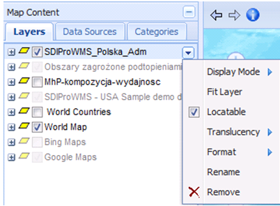
The following features for layers are available:
Menu Item |
Description |
Display mode |
Set options for the quality and efficiency for displaying layers on the map. Two modes are available: buffer view and tiling. |
Fit layer |
Adjust the map window so the entire layer is visible. |
Locatable |
If enabled, highlight and select features on the map. This is required for the Feature info command to work properly. |
Translucency |
Define the transparency for the layer. |
Format |
Change the format in which data is presented on a map, for example, .png, .jpeg, .svg, .svgz, and .gif. |
Rename |
Change the name of the layer. |
Remove |
Remove a layer from the map content. You can also remove layers by selecting the layer and clicking Delete. |
Filter |
Filters the vector data by attribute values. It applies only to data derived from sources such as WFS, MPS, and EGIS. |
Data Sources
The Data Source tab contains information about data sources and maps. Entries are grouped by source/data providers.
Categories
The Categories tab lets you arrange all available layers into groups. The structure of services that provide data with hierarchic structure (layers grouped into categories) is visible in the Categories tab.
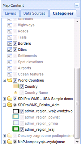
The right-click menu for layers is also available in the Categories tab. The following are the available options:
Menu Item |
Description |
|---|---|
Fit layer |
Adjust the map window so the entire layer is visible. |
Locatable |
If enabled, highlight and select features on the map. This is required for the Feature info command to work properly. |
Visible |
Control displaying the layer. |
Rename |
Change the name of the layer. |
Remove |
Remove a layer from the map content. You can also remove layers by selecting the layer and clicking Delete. |
Filter |
Filters the vector data by attribute values. It applies only to data derived from sources such as WFS, MPS, and EGIS. |
![]() The Locatable option is not available in the right-click menu for the entire group, but only for single layers in the group.
The Locatable option is not available in the right-click menu for the entire group, but only for single layers in the group.
| Top of Page |